Single-mode lasers are widely used in various fields such as biomedical applications, food testing, and chemical substance detection.
The main content of this issue includes initial parameter design, lens data, merit function, and optimization results, with a detailed explanation provided for each part.
Initial parameters generally cover system aperture, field of view, wavelength, and material library. The system aperture can be set as entrance pupil diameter, F-number, or NA (Numerical Aperture) according to different requirements.
Lens parameters usually include aperture stop position, lens radius of curvature, lens thickness, lens material, and lens aperture. During the initial design phase, targeted design should be conducted: the edge of the lens should not be too thin, the overall thickness should not be excessively large, the material should be replaced with commonly used ones, and the aperture should reserve space for structural support.
The merit function typically includes constraints on total length, focal length, edge conditions, and aberration, which need to be customized based on actual performance indicators.
The main content of this issue can be outlined as follows:
- Initial Parameter Design
- Lens Data Design
- Merit Function Design
- Lens Optimization and Results
- Conclusion
Explanations for the above sections are as follows:
The initial parameter settings are shown in Figure 1. The output beam of a single-mode fiber has a certain divergence angle, which is defined here as the object-space NA with a value of 0.12. You can also design the parameters based on the actual divergence angle of the purchased fiber. The apodization type is Gaussian with an apodization factor of 1, and afocal image space is selected.
Meanwhile, it is necessary to set the field of view, wavelength, and material. The field of view is defined as the object height, which equals the core diameter of the fiber. The preset wavelength is 532 nm, and the glass material is selected from Chengdu Guangming Glass.
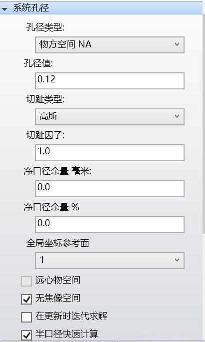
Figure 1: Initial Parameter Design
The lens data is shown in Figure 2. It includes the radius of curvature—all radii of curvature in this lens are set as variables, and the optimization results are presented in the figure. For lens thickness design, the object distance is also treated as a variable. The material is the glass optimized by the hammer optimization method, which can be replaced and further optimized based on whether it is a commonly used glass. Finally, regarding the lens aperture, space must be reserved for optomechanical assembly.
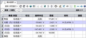
Figure 2: Lens Data Design
The merit function design is shown in Figure 3. The merit function of this lens shares similarities with the beam expander discussed in the previous issue, including boundary constraints and image height constraints. The difference lies in that this lens is a finite-distance lens: its focal length is related to the beam divergence angle and beam diameter. The output beam diameter can be calculated based on the required focal length, or the focal length can be derived from the required output beam diameter.
It is only necessary to constrain either the focal length or the output beam diameter here.
Similarly, the MNCA and MNEA operands are used to constrain the air gap, and the REAY operand is employed to constrain the output beam diameter.
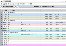
Figure 3: Merit Function Design
The lens optimization results are shown in Figure 4. Lens 1 and Lens 2 form the collimating lens group. Through the optimization of parameters such as radius of curvature and thickness, the final design meets the actual performance requirements.
The divergence angle is shown in Figure 5. It can be seen from the figure that the divergence angle of the output beam is smaller than the diffraction limit, satisfying the requirements for both the size and collimation of the output beam.
The design of the fiber collimating lens parameters is completed. For subsequent tolerance analysis, you can conduct evaluation and assessment based on this design.
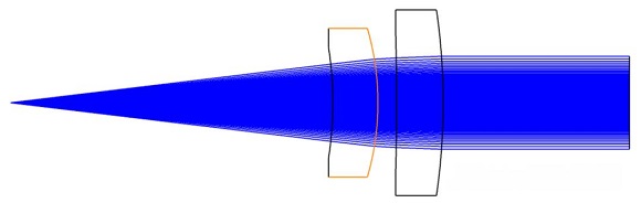
Figure 4: 2D Diagram of Lens Architecture
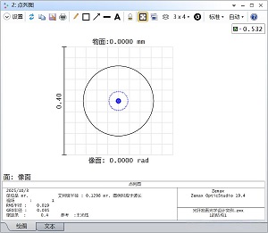
Figure 6: Lens Spot Diagram
- A 2-lens configuration is often used for single-wavelength fiber collimating lenses.
- Generally, the output beam diameter is approximately 5 mm, which matches the focused spot size or the entrance pupil of the objective lens.


