The core content of this issue focuses on the design of the galvanometer + F-theta lens optical system, including multi-configuration modeling of a single-axis galvanometer and F-theta lens design. The F-theta lens can be optimized either by setting the field of view (FOV) or through systematic optimization of the galvanometer + F-theta lens combination.
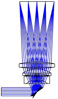
This issue shares a design example of a galvanometer + F-theta lens optical system.
The combination of a galvanometer and an F-theta lens is a common optical system configuration, widely used in laser processing, scanning imaging, beam control, and other fields. By integrating the high-speed deflection capability of the galvanometer with the focusing characteristics of the F-theta lens, the system achieves efficient and precise beam positioning and processing.
A galvanometer typically consists of a high-speed driven mirror that can rapidly change the propagation direction of the laser beam, while the F-theta lens is responsible for focusing the laser onto the target plane, ensuring the precision and uniformity of the light spot. This combination not only improves the system’s response speed but also significantly enhances optical performance, enabling excellent performance in complex application scenarios.
Major international galvanometer manufacturers include Scanlab, Cambridge Technology, Thorlabs, etc., while key domestic manufacturers include Beijing Century Sunny, Jinhai Chuang, etc. Selection can be based on requirements for spot size, rotation speed, and precision.
The core content of this issue focuses on the design of the galvanometer + F-theta lens optical system, including multi-configuration modeling of a single-axis galvanometer and F-theta lens design. The F-theta lens can be optimized either by setting the field of view (FOV) or through systematic optimization of the galvanometer + F-theta lens combination.
During the design process, factors such as scanning angle, working distance, and imaging quality must be comprehensively considered to reasonably select the focal length and optical path structure of the F-theta lens. Ray tracing of multi-configurations using optical simulation software can effectively analyze distortion, focused spot size, and energy distribution characteristics. Optimizing the spherical parameters of the F-theta lens for laser beams with different incident angles can significantly reduce aberrations and improve scanning precision. In practical applications, it is also necessary to match the dynamic response performance of the galvanometer to ensure the system maintains good focusing stability and repeat positioning accuracy even under high-speed scanning.
First, let’s look at the final design results, as shown in Figures 1 and 2. Figure 1 depicts the scanning system in a single-angle deflection state, while Figure 2 presents a collection of galvanometer deflection angles in multi-configurations, providing an intuitive view of the overall scanning results and range.
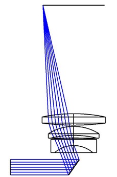
Figure 1: Single-angle scanning result
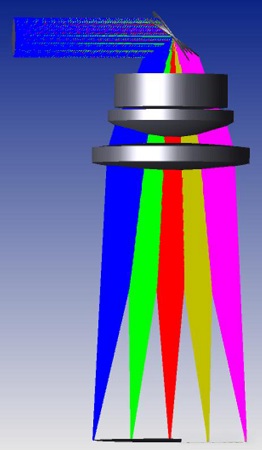
Figure 2: Multi-configuration scanning set
Next, the design process and structure of the galvanometer and F-theta lens will be detailed, covering the following aspects:
1. Initial Parameter Setting
Initial parameters include system data, field of view,wavelength, and material:System data is filled in according to actual requirements; here, the entrance pupil diameter is 12mm.The field of view uses default settings.The wavelength is 532nm.The material is Chengdu Guangming (CDGM); fused silica can also be selected.The specific setting results are shown in Figure 3.
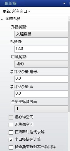
Figure 3: Parameter settings
2. Establishment of Multi-Configurations
The establishment of multi-configurations mainly involves editing scanning angles for multiple configurations:First, create a mirror model by clicking the mirror icon on the interface (as shown in Figure 4).Then, add coordinate breaks before and after the mirror respectively.The final result is shown in Figure 5, and the multi-configuration design result is presented in Figure 6.
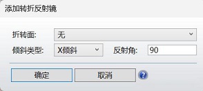
Figure 4: Mirror settings
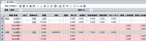
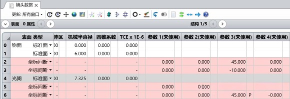
Figure 5: Mirror modeling
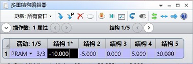
Figure 6: Multi-configuration result
3. Lens Data
The final lens data is shown in Figure 7, including data for the mirror, deflected multi-configurations, and F-theta lens.
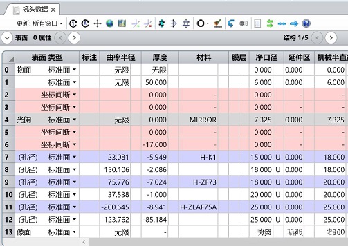
Figure 7: Lens data
4. Optical Design Results
The final design result is shown in Figure 8:
Figure 8: Galvanometer + F-Theta Lens Optical System Architecture
The design of the galvanometer + F-theta lens optical system is completed.