This issue focuses on the optical design of laser processing systems.
As one of the four great inventions of modern times, lasers have found increasingly widespread applications with the advancement of science and technology. Particularly in the field of laser processing, they have fundamentally transformed processing methods while achieving superior processing quality and efficiency.
The laser processing system discussed in this issue features a spatially output laser beam with a divergence angle on the order of milliradians (mrad). The optical components of the laser processing system mainly consist of four modules: the beam expanding and collimating module, beam transmission module, galvanometer module, and field lens module. In practical applications, aside from the laser processing optical system, there is also a real-time processing monitoring optical system, which will not be elaborated on here but will be designed and explained in subsequent discussions.
As shown in Figure 1, this diagram illustrates the laser processing optical system. The design of such a system involves several considerations: first, the design of the laser beam expansion ratio (whether to use 2x, 3x, or another ratio) requires overall evaluation; additionally, the selection of galvanometers and the determination of lens focal lengths must be based on theoretical analysis and calculations.
Here, a formula that runs through the entire laser processing process needs to be explained:

In the formula, M² represents the beam quality factor, typically ranging from 1.1 to 1.2. It denotes the ratio of the product of the waist radius and far-field divergence angle of an actual beam to that of a fundamental Gaussian beam. λ is the laser wavelength, f is the focal length of the focusing lens, π is the (pi), and D is the beam diameter after expansion.
For a laser processing system, requirements serve as the input and objectives of the design. Generally, a smaller focused spot is desired, with the theoretically calculated minimum focused spot typically around 10μm. For a given laser source, the wavelength is fixed, so the design variables include the field lens focal length and beam diameter.
The focused spot is proportional to the focal length: a shorter focal length results in a smaller focused spot. In practical processing, the minimum focal length used is generally between 50mm and 60mm, primarily considering that the reserved back focus in actual processing cannot be too short. Additionally, shorter focal lengths require more spherical lenses in the optical design to correct aberrations.
Once the above factors are appropriately considered, the entrance pupil diameter and beam diameter after expansion need to be evaluated. From the formula, the beam diameter is inversely proportional to the focused spot: a larger beam diameter leads to a smaller focused spot. However, a larger beam diameter increases spherical aberration in the optical system, requiring more lenses and greater difficulty in aberration correction. Therefore, the beam diameter after expansion is generally around 10mm. If the beam diameter is near the paraxial region, a custom design is feasible without the need to purchase a field lens (field lenses, which are typically matched to larger beams, are relatively expensive).
For a post-expansion beam diameter of 5mm or less, a plano-concave lens combined with a plano-convex lens is sufficient for beam expansion. These lenses can be directly purchased as off-the-shelf products. To quantitatively analyze whether the divergence angle of the combined system is on the order of mrad or μrad, simply import the lens parameters into Zemax for simulation.
If the post-expansion diameter is around 10mm, a custom design is necessary to meet performance (specifications).
Galvanometer selection is generally based on the post-expansion beam diameter. Galvanometers are differentiated into X-axis and Y-axis, with corresponding drive board connections. The control module is typically either custom-developed or sourced from marking software and control cards.
The laser processing optical system shown in Figure 1 operates at a wavelength of 1064nm, with an initial laser beam diameter of 1mm. The beam expander has a 12x magnification, resulting in a post-expansion diameter of 12mm. The galvanometer system includes X-axis and Y-axis components with a 20mm spacing, and the distance from the Y-axis galvanometer to the field lens is 17mm. The field lens consists of 3 lenses with a focal length of 90mm.
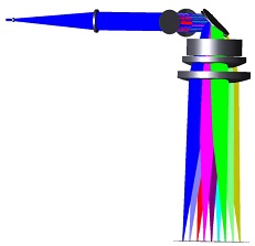
Figure 1 Laser Processing Optical System
The lens data of the laser processing optical system is shown in Figure 2, and the multi-configuration data is shown in Figure 3.
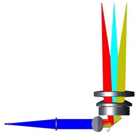
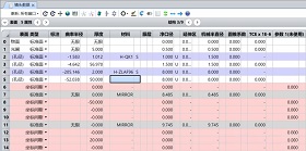
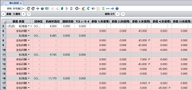
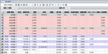
Figure 2 Lens Data of the Laser Processing Optical System 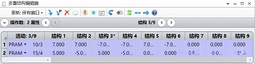
Figure 3 Parameter Settings for Galvanometer Multi-Configuration
This concludes the introduction to the laser processing optical system.


