


As a core process in the manufacturing of optical components, optical coating is widely applied to key parts such as camera lenses, sensor protection windows, and optical filters. By precisely controlling the material, number of layers, and thickness of the thin film, it regulates the reflection, transmission, and beam splitting properties of light, directly influencing the imaging quality of optical systems. The following systematically organizes the basic theory and technical key points of optical coating from four aspects: film definition, classification, process principles, and methods.
1. What is an Optical Film?
An optical film refers to a single or multi-layer thin, uniform functional film deposited on the surface of optical components (e.g., camera lenses, sensor optical glass) through specific processes. Its materials can be dielectric films (such as silicon dioxide, titanium dioxide), metal films (such as aluminum, silver), or composite films of the two.
From the perspective of optical principles, when light passes through this layered medium, the reflected and transmitted light from the upper and lower interfaces of the film generates a multi-beam interference phenomenon in the incident and reflection directions. Utilizing this characteristic, people artificially control the interference effect of light by designing the material combination of the film (e.g., alternating stacking of high/low refractive index materials), single-layer thickness (usually 1/4 or 1/2 of the target wavelength), and total number of layers. This achieves the redistribution of light energy—for example, reducing useless reflection, enhancing effective transmission, or accurately filtering light of specific wavelengths to meet the performance requirements of different optical systems.
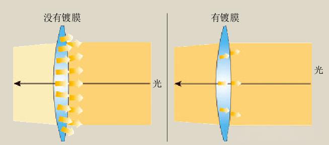
Taking camera lenses as an example, the optical film on their surface can reduce stray light caused by light reflection, preventing lens flare or ghosting in images due to the sensor receiving excess light. At the same time, it improves the light transmittance of the lens, ensuring the clarity and contrast of the image.
2. Core Classification of Optical Films
According to functional requirements, optical films can be divided into five categories. Different types of films play distinct roles in optical systems, which are explained below in combination with application scenarios such as cameras and projection equipment:
(1) Anti-Reflection (AR) Coating: Reducing Reflection, Enhancing Transmission
The anti-reflection coating is the most widely used optical film. Its core function is to reduce the reflectance of the optical surface while increasing transmittance. The principle is to achieve destructive interference of reflected light from the upper and lower interfaces of the film, offsetting part of the reflected light energy.
- Performance Indicators: For a single wavelength (e.g., laser), the reflectance can theoretically be reduced to 0% and the transmittance to 100%; for the visible spectrum (400-760nm), the reflectance can be as low as 0.5% or less in practical applications, and some high-precision AR coatings can even achieve an ultra-low reflectance of 0.1%.
- Application Scenarios: Since it can effectively reduce reflection losses in multi-lens systems (such as the multi-group lenses of a camera) and avoid the accumulation of stray light, the AR coating has become a "standard configuration" for modern optical devices. It is used in everything from daily myopia glasses (reducing mirror reflection and improving visual comfort through AR coatings) to camera lenses and projection lenses, all relying on it to improve light transmission efficiency and imaging quality.
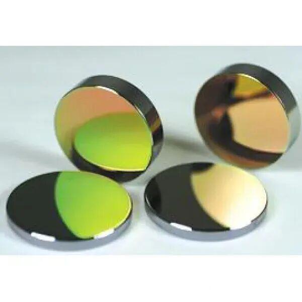
(2) High-Reflection (HR) Coating: Enhancing Reflection, Focusing Energy
The core function of the high-reflection coating is to reflect most of the incident light energy. According to different materials, it can be divided into metal high-reflection films and dielectric high-reflection films:
- Metal Films: Made of metal materials such as aluminum and silver, with a reflectance of 85%-98%. However, they have certain absorption losses and are suitable for scenarios where reflection efficiency is not extremely demanding (e.g., ordinary mirrors).
- Dielectric Film Stacks: Formed by alternating stacking of high-refractive index (e.g., TiO₂) and low-refractive index (e.g., SiO₂) dielectric materials. Due to the absence of metal absorption losses, as the number of film layers increases (usually 10-50 layers), the reflectance can approach 100% (some high-precision dielectric HR coatings have a reflectance of over 99.9%).
- Application Scenarios: In laser manufacturing, HR coatings are a core component of resonant cavities; in camera modules, some optical filters (e.g., infrared mirrors) also rely on HR coatings to achieve total reflection of light of specific wavelengths.
(3) Beam Splitter Coating (Neutral Density Splitter): Distributing Light Energy Proportionally
The beam splitter coating (also known as a neutral density splitter) can divide the incident light energy into two beams—transmitted and reflected—according to a fixed ratio without changing the spectral characteristics of the light (i.e., no color shift). The most typical ratio is Transmittance (T) : Reflectance (R) = 50:50, and ratios such as 70:30 or 30:70 can also be designed according to requirements.
- Application Scenarios: In camera testing equipment, the beam splitter coating can split the same test light into two paths—one for calibrating the light source and the other for detecting the imaging performance of the camera; in projection systems, it can also be used to control the splitting of light.
(4) Spectral Beam Splitter Coating: Filtering Light by Wavelength
The core function of the spectral beam splitter coating is to distribute light energy according to wavelength ranges—allowing light of a specific spectral range to transmit and reflecting light of another spectral range. It is mainly divided into two types:
- Short-Wave Pass (SWP) Cutoff Filter Coating: Allows short-wave light (e.g., blue light, green light) to transmit and reflects long-wave light (e.g., red light, infrared light).
- Long-Wave Pass (LWP) Cutoff Filter Coating: Allows long-wave light to transmit and reflects short-wave light.
- Application Scenarios: In the field of color imaging, the spectral beam splitter coating is the key to achieving "color separation". For example, it splits white light into three primary colors (red, green, blue), which are respectively received by the RGB sensor of the camera and finally combined into a color image. Additionally, it is indispensable in fields such as color projection, color printing, and TV displays.
(5) Interference Filter: Precisely Filtering Specific Wavelengths
The interference filter is a high-precision spectral filtering component made based on the principle of multi-beam interference. It is usually composed of multiple film layers (10-100 layers) and can only allow light of a specific wavelength range to pass, while blocking light of other wavelengths. It is mainly divided into two types:
- Cutoff Filters: Divide the spectrum into a "cutoff region" (where light cannot pass) and a "passband region" (where light can pass fully). They include the aforementioned short-wave pass filters and long-wave pass filters. Their film structure is mostly a periodic stack of alternating high/low refractive index materials to enhance the interference effect.
- Bandpass Filters: Only allow light of a narrow wavelength range to pass (e.g., a green bandpass filter with a central wavelength of 550nm and a bandwidth of 20nm), and are often used in scenarios such as spectral analysis and fluorescence detection.
- Application Scenarios: In camera modules, the Infrared Cutoff (IR-Cut) Filter is a typical long-wave pass cutoff filter. It can block infrared light from entering the sensor, avoiding interference with visible light imaging and ensuring the authenticity of image colors.
3. Definition and Process Principle of Optical Coating
1. Process Definition of Optical Coating
Optical coating refers to the process of depositing single or multi-layer metal/dielectric films on the surface of optical components through physical or chemical methods. Its core purpose is to achieve the "regulation" of light through the optical properties of the film—including reducing reflection (anti-reflection), increasing reflection (high reflection), beam splitting (energy/spectral beam splitting), filtering (wavelength selection), and polarization (controlling the polarization direction of light)—to meet the specific performance requirements of optical systems.
Common optical coating methods can be divided into two categories: vacuum coating (the mainstream form of physical coating) and chemical coating. Different methods have significant differences in process characteristics and applicable scenarios.
2. Core Principle of Optical Coating: Light Interference
The essence of optical coating is to utilize the "light interference" phenomenon, and its principle can be elaborated as follows:
When light irradiates the surface of an optical component with a coating, it undergoes reflection and transmission at the upper interface (air-film interface) and lower interface (film-substrate interface) of the film, forming multiple beams of reflected and transmitted light. These beams have the same frequency and a fixed phase difference, satisfying the "interference conditions". By controlling the refractive index (n) and thickness (d) of the film, the reflected light of a specific wavelength can undergo "destructive interference" (energy cancellation, reducing reflection) or "constructive interference" (energy superposition, enhancing reflection), while correspondingly regulating the energy of the transmitted light.
For example, an anti-reflection coating is usually designed as a "1/4 wavelength film" (i.e., the film thickness d = λ/(4n), where λ is the target wavelength and n is the refractive index of the film). In this case, the phase difference between the reflected light from the upper and lower interfaces is π, resulting in destructive interference and thus reducing the reflectance. A high-reflection coating, on the other hand, uses multiple sets of 1/4 wavelength film stacks (alternating high/low refractive index materials) to make the reflected light from each layer undergo constructive interference, which, when superimposed, increases the reflectance.
4. Mainstream Optical Coating Methods
According to the "film deposition method", optical coating methods are divided into two categories: chemical coating and physical coating. The two have their own advantages and disadvantages in process control, film performance, and applicable scenarios:
(1) Chemical Coating: Film Deposition Based on Chemical Reactions
Chemical coating is a process that "grows" a film on the surface of optical components using chemical reactions. Its core is to control the reaction conditions (such as solution concentration, temperature, and time) to ensure the uniform deposition of the film material on the substrate surface. There are two common chemical coating methods:
1. Dip Coating
- Process Flow: First, prepare a chemical solution containing corresponding ions according to the composition of the target film (e.g., sodium silicate solution is used to prepare a silicon dioxide film); heat the cleaned optical glass (e.g., camera sensor protection window) to a specific temperature (usually 40-80℃) and immerse it in the prepared solution; after a chemical reaction occurs between the solution and the glass surface to form a film, take out the glass and complete the coating through drying (100-200℃) and curing processes.
- Core Advantages: It is currently the only method that can deposit films on both sides of optical components simultaneously. It has low equipment costs and simple operation, making it suitable for mass production.
- Limitations: The film thickness uniformity is poor (easily affected by the solution concentration gradient), the film strength is low, and it is difficult to prepare multi-layer films. It is suitable for scenarios with low precision requirements (e.g., anti-reflection treatment of ordinary glass).
2. Spray Coating
- Process Flow: Dissolve or disperse the film material in a solvent to prepare a sprayable "film solution"; uniformly spray the film solution onto the surface of the optical component using a spray gun; form a solid film through drying (to remove the solvent) and high-temperature curing (e.g., 300-500℃ to enhance film adhesion).
- Core Advantages: It can flexibly control the coating area (e.g., coating only a local part of the lens) and is suitable for irregular optical components.
- Limitations: The film thickness control precision is low (more than ±5%), the film density is poor, and pinholes and bubbles are prone to occur. It is only used for low-precision optical components.
(2) Physical Coating: Film Deposition Based on Physical Processes
Physical coating is a process that "transfers" coating materials to the surface of optical components through physical means (such as evaporation and sputtering) in a vacuum environment to form a film. Its core advantages include high film thickness uniformity (within ±1%), strong film density, good adhesion, and the ability to prepare complex multi-layer film stacks. It is the mainstream coating method for high-precision optical components (such as camera lenses and laser lenses).
1. Vacuum Evaporation
- Process Flow: Place the optical components and coating materials (e.g., aluminum, titanium dioxide) in the vacuum chamber of a vacuum coating machine, and evacuate to a pressure of 10⁻³-10⁻⁵Pa (to prevent air molecules from affecting the film quality); heat the coating material through resistance heating or electron beam bombardment to evaporate it into gaseous atoms/molecules; these gaseous particles move at a constant speed in the vacuum environment, deposit on the surface of the optical components, and form a film after cooling; during the process, an optical monitor can be used to measure the film thickness in real time to ensure precision.
- Application Scenarios: Suitable for preparing single or multi-layer dielectric films and metal films, such as anti-reflection films and high-reflection films for camera lenses.
- Advantages: High film purity (no chemical impurities), fast deposition speed (a single layer can be completed in a few seconds to a few minutes), and relatively low cost.
2. Ion Plating
- Process Flow: In a vacuum chamber, generate ions through gas discharge (e.g., argon discharge); accelerate the ions using an electric field to bombard the surface of the coating material, "sputtering" the material into gaseous particles; with the assistance of ions, these particles deposit more uniformly and densely on the surface of the optical components to form a film.
- Core Advantages: The adhesion between the film and the substrate is extremely strong (3-5 times that of vacuum evaporation), it can achieve uniform coating on the surface of curved and irregular parts, and the film has better wear resistance and corrosion resistance.
- Application Scenarios: Suitable for scenarios requiring high film strength, such as automotive camera lenses (which need to withstand harsh environments) and military optical components.
- Limitations: High equipment costs and slow deposition speed, making it suitable for high-precision, small-batch production.
3. Magnetron Sputtering
- Process Flow: Introduce an inert gas (e.g., argon) into the vacuum chamber, apply a high voltage between the cathode (target made of coating material) and the anode (optical component) to form a composite field of magnetic and electric fields; electrons are confined in the composite field and collide with argon molecules to generate argon ions; the argon ions bombard the surface of the target, causing the target atoms to be "sputtered" out and deposited on the surface of the optical components to form a film.
- Core Advantages: Extremely high film thickness uniformity (within ±0.5%), precise control of film composition (e.g., preparation of alloy films and composite films), and deposition at low temperatures (avoiding high-temperature damage to optical components).
- Application Scenarios: It is the preferred coating method for camera sensor protection windows and high-precision optical filters, especially suitable for preparing complex multi-layer film stacks (such as the multi-layer dielectric film of an IR-Cut filter).
Conclusion
Through the precise design and preparation of films, optical coating realizes the "controllable regulation" of light and is a key process for improving the performance of optical systems. From the anti-reflection film of camera lenses to the high-reflection film of laser equipment, from the spectral beam splitter film for color imaging to the IR-Cut filter of sensors, optical coating runs through the entire process of optical component manufacturing. In practical applications, it is necessary to select the appropriate film type and coating method according to the functional requirements, precision requirements, and service environment of the optical components to balance performance, cost, and production efficiency.